Use Case_DJI Phantom4 RTK Drone in Topographical Survey in Saadiyat Lagoons District Enabling Works at Abu Dhabi, United Arab Emirates
Sanju Mathew, Sales Manager, Aeromotus Dubai (DJI Enterprise Drone Solution
GeoDrones Aerial Services, Dubai, United Arab Emirates
Summary and Scope
Summary / Findings from POC
| Camera Model | Phantom 4 RTK |
| Area Covered | 622 Ha |
| Total Flight Time | 650 minutes |
| No of Images Captured | 11,219 |
| Total Size of Raw Images | 89 GB |
Survey Location
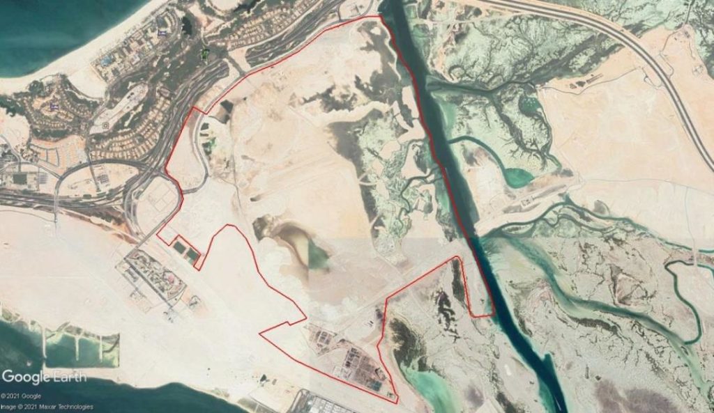
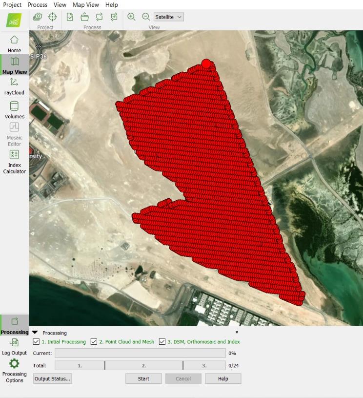
The location of the Survey Area is shown on Google Earth below. The KML of the Project boundary was created using coordinates provided by the client. The total area of the project is 622 Hectares (6.22 sqkm).
HSE
Drones for Survey & Measurement
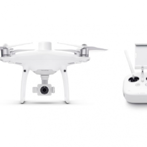
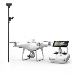
- DJI Phantom 4 RTK Drone with DJI’s DRTK Mobile Station for Phantom Series.
-
DJI ENTERPRISE, DJI PHANTOM
DJI Phantom 4 RTK SDK
0 out of 5(0)The Phantom 4 RTK SDK package is essentially the same as the market leading Phantom 4 RTK except that it includes the Phantom 4 RTK SDK Remote Controller without screen. In addition to supporting Ground Station Pro, pilots with experience using 3rd party applications on DJI drones are able to access the world’s leading drone app ecosystem for their Phantom 4 RTK with the SDK remote controller. Users can plug in a compatible Android or iOS device and install any compatible DJI Mobile SDK-enabled app to harness the full power of their Phantom 4 RTK
SKU: n/a -
DJI ENTERPRISE, DJI PHANTOM, RTK/PPK
DJI Phantom 4 RTK Quadcopter with D-RTK 2 GNSS Mobile Station Combo
DJI ENTERPRISE, DJI PHANTOM, RTK/PPKDJI Phantom 4 RTK Quadcopter with D-RTK 2 GNSS Mobile Station Combo
0 out of 5(0)- Enterprise-Level Drone Mapping Solution
- 1cm+1ppm RTK Horizontal Accuracy
- 1.5cm+1ppm RTK Vertical Accuracy
- Distortion Calibrated 1″ CMOS Sensor
- TimeSync Alignment for Accurate Metadata
- Controller with Display and GS RTK App
- Photogrammetry & Waypoint Flight Modes
- OcuSync for up to 4.3-Mile Streaming
- Up to 30 Minutes Flying Time
- D-RTK 2 GNSS Mobile Station Included
SKU: n/a
Methodology
1. Pre – Survey
- The mission plans were created using DJI’s GS RTK App on DJI Smart Controller.
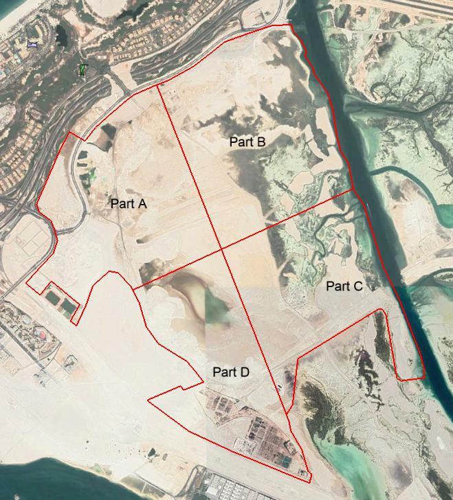
- The total project area is approx. 622 hectares. The entire area was divided into 4 parts viz. Part A, Part B, Part C and Part D as shown in the figure below.
The flight altitude was set to 70m above ground. - The side overlap was set to 65% and front overlap was set to 75%.
2. Realtime Georeferencing at Site
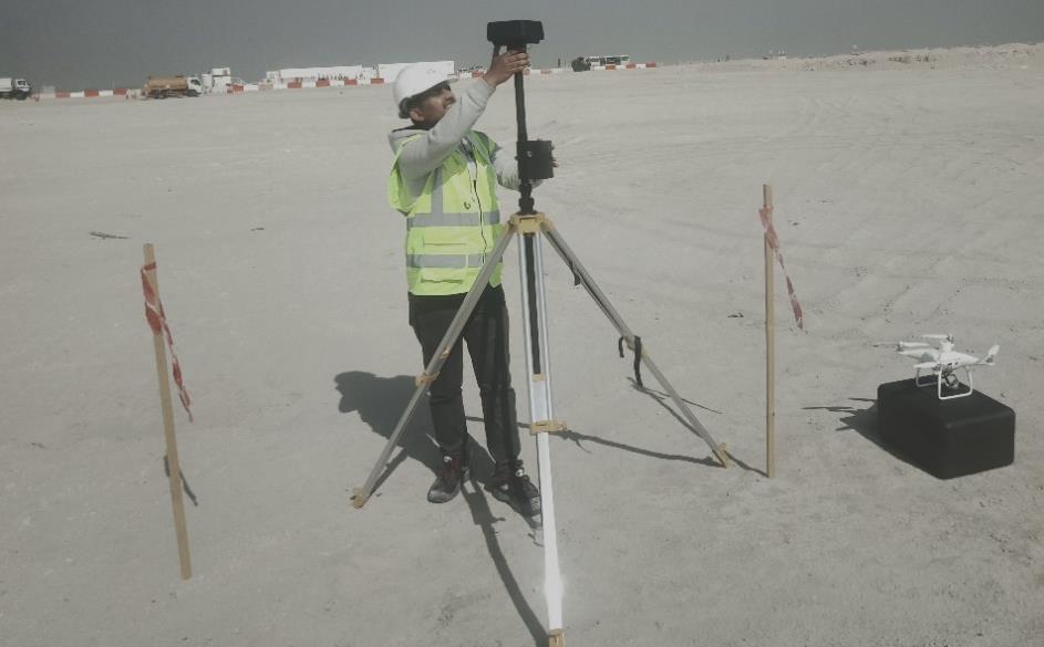
- Setting up D-RTK-2
- DJI D-RTK2 Base Station was setup at 4 different points for each part.
- The coordinates provided on site were as follows.
| Pt | Part | Easting (m) | Northing (m) | Z (m) |
| 1 | A | 240738.251 | 2715642.131 | 01.01.41 |
| 2 | B | 241901.596 | 2716140.233 | 01.01.87 |
| 3 | C | 242539.287 | 2714990.261 | 01.02.05 |
| 4 | D | 241744.300 | 2714105.369 | 01.03.16 |
| 5 | A | 240889.792 | 2715561.828 | 01.01.90 |
| 6 | B | 241610.667 | 2716001.361 | 0.929 |
| 7 | C | 242478.952 | 2714583.717 | 01.01.87 |
| 8 | D | 241922.728 | 2714251.512 | 01.03.73 |
- The above coordinates were obtained using Municipality 4425 point as base point.
- GeoDrones used Pt. 1,2,3 and 8 for D-RTK2 setup in Part A, B, C and D respectively.
- The coordinates recorded by D-RTK2 base station at the 4 points were as follows.
| Pt | Part | Latitude (dd) | Longitude (dd) | Altitude (Ell.Ht in m) |
| 1 | A | 24.53297324 | 54.44090817 | -31.94607735 |
| 2 | B | 24.53767251 | 54.45230393 | -30.68410301 |
| 3 | C | 24.52740566 | 54.45880513 | -29.53209877 |
| 8 | D | 24.52064782 | 54.45284978 | -29.85610199 |
3. Phantom 4 RTK flights
- High resolution RTK geotagged images were captured with 70% overlap covering entire area.
- 11,219 RTK fixed images were acquired.
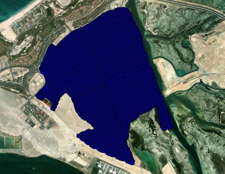
- Total 26 flights were flown for topographic survey covering the entire project area.
- Flight summary is shown below:
| Part | Flights | Flight Distance (km) |
| A | 7 | 47.51 |
| B | 7 | 53.34 |
| C | 6 | 42.46 |
| D | 6 | 40.35 |
4. Data Processing
- Orthomosaic Generation using DJI Terra Software
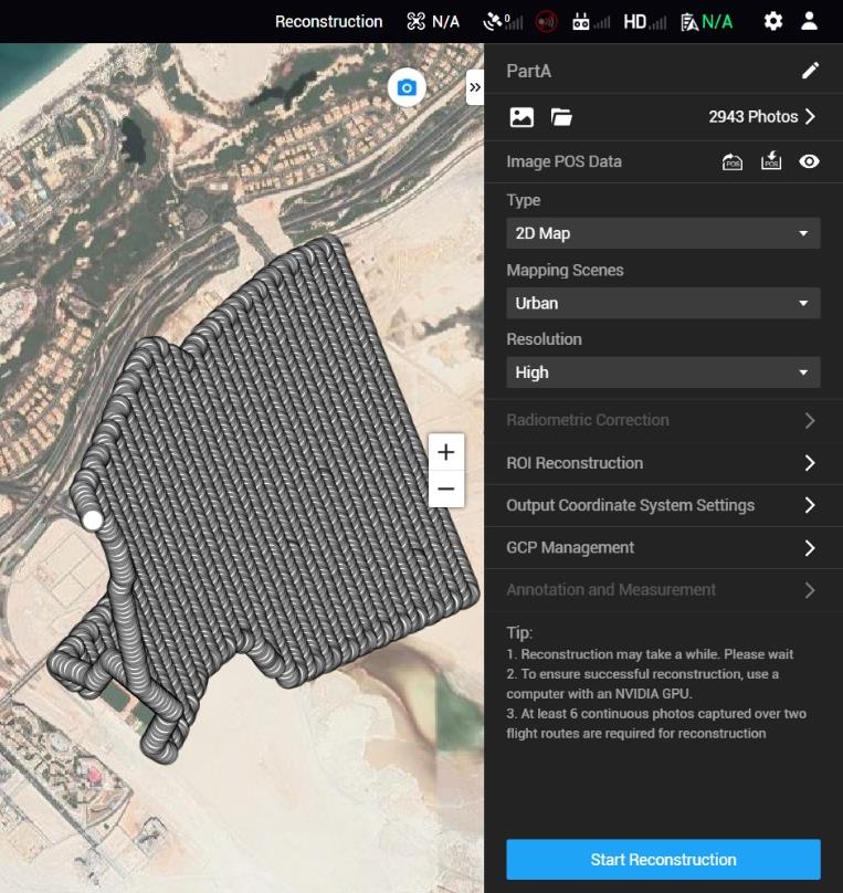
- The images were processed part by part using DJI Terra software.
- High resolution orthomosaic images were generated in .tif format.
- Used the following checkpoints to assess the positional accuracy of the generated orthomosaics. Following results were observed.
| Pt | Part | E_GD (m) | N_GD (m) | E_CLIENT (m) | N_CLIENT (m) | dx | dy |
| 1 | D | 241971.428 | 2713903.196 | 241971.401 | 2713903.202 | 0.027 | -0.006 |
| 2 | C | 243129.608 | 2714749.098 | 243129.568 | 2714749.113 | 0.040 | -0.014 |
| 3 | B | 241337.055 | 2716716.884 | 241337.093 | 2716716.843 | -0.037 | 0.040 |
| 4 | B | 241757.968 | 2716978.033 | 241758.006 | 2716977.990 | -0.037 | 0.042 |
| 5 | A | 240591.755 | 2715599.631 | 240591.741 | 2715599.698 | 0.014 | -0.066 |
| 6 | A | 240237.137 | 2715079.432 | 240237.134 | 2715079.487 | 0.003 | -0.055 |
- The differences we observed were less than 7cm in coordinates (Easting, Northing and Elevation)
Point Cloud, Digital Terrain Model (using Pix4D Mapper)
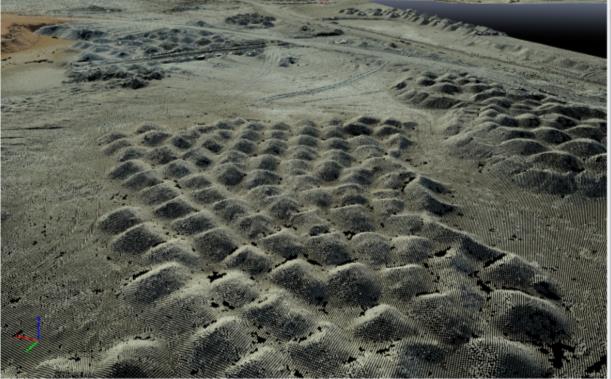
- All Images were processed in Pix4D software for generation of 3D outputs viz. Classified Point Cloud, DTM, etc.
- Classified Point Cloud in .las format was generated.
- DTM was generated in .tif format.
Point Grid File (with 1m x 1m Grid) in ASCII format
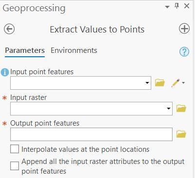
- 1m x 1m Grid for XYZ file was generated using Extract Values to Points tool in ArcGIS Pro.
- Following was the method
- 1m Grid file generated using DSM of a part was loaded.
- DTM of that part was loaded.
- All the Points were given values of the raster cells of the DTM, which is stored as elevation.
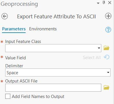
- After the values were extracted from the DTM, the table was then exported to ASCII .txt format using Export Feature Attribute to ASCII tool in ArcGIS Pro.
- Following was the method
- The extracted table was selected as input.
- Raster Values were selected as Value field
Contact form
Email us with any questions or inquiries or use our contact data. We would be happy to answer your questions.

